Connecting an External LED to the micro:bit
In this lesson, students extend their understanding of physical computing by adding an external LED circuit to their micro:bit project. Building on their previous countdown timer and maker activity, students learn how to safely connect an LED and correctly orient its positive and negative legs.
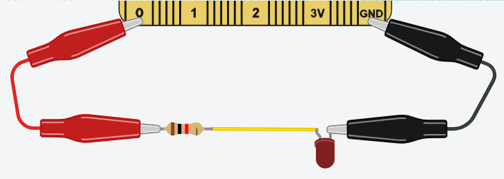
Students explore how electricity flows through a circuit and how the micro:bit can control that flow using its pins. The LED is connected by running a wire from a micro:bit pin (such as Pin 0), through a resistor, into the LED’s positive leg, and then back to ground (GND), completing the circuit.
Materials
-
Connecting an LED to the micro:bit
https://support.microbit.org/support/solutions/articles/19000101863-connecting-an-led-to-the-micro-bit -
Which Resistor Should I Use with my LED?
https://kitronik.co.uk/blogs/resources/which-resistor-should-i-use-with-my-led -
Example MakeCode for adding LEDs
https://makecode.microbit.org/_imPV5u5FgdLK
Activity Instructions
- Introduce the activity
- If this activity build on the countdown timer craft let students know – Last time we programmed a micro:bit so your project could count down. Today, we’re going to make it light up.
- If this is a new standalone activity tell students – today we are going to add an external LED to the micro:bit and connect it with alligator clips.
- Introduce the LED
- This is a Light Emitting Diode—an LED. It lights up when electricity flows through it.
- Teach explicitly:
- LEDs only work in one direction
- Long leg = positive (+)
- Short leg = negative (–)
- If connected backwards, it won’t work
- **Depending on the size of the LED – We may also need a resistor to protect it—too much current can burn out the LED.
- Program the LED
- First lets program the micro:bit to control the light with code.
- Model in MakeCode:
- On button A pressed → set pin 0 to 1 (ON)
- On button B pressed → set pin 0 to 0 (OFF)
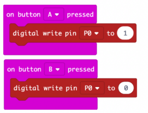
- A 1 sends power. A 0 stops it. That’s how your code controls the real world.
- Build the Circuit
- Let’s connect your LED so your micro:bit can control it.
- Model step-by-step:
- Connect:
- Pin 0 → (**resistor) → LED long leg (+)
- LED short leg → GND
- Use alligator clips or breadboard
- This creates a complete circuit—electricity can now flow in a loop. The micro:bit provides power from a pin to control the LED
- Connect to Project
- Now go back to your countdown project—how can light make it better?
- Discuss:
- “Where should the light go?”
- “What does it communicate?”
- “How does it improve your design?”
- Test & Iterate
- Share & Reflect
- Introduce the activity
- If this activity build on the countdown timer craft let students know – Last time we programmed a micro:bit so your project could count down. Today, we’re going to make it light up.
- If this is a new standalone activity tell students – today we are going to add an external LED to the micro:bit and connect it with alligator clips.
- Introduce the LED
- This is a Light Emitting Diode—an LED. It lights up when electricity flows through it.
- Teach explicitly:
- LEDs only work in one direction
- Long leg = positive (+)
- Short leg = negative (–)
- If connected backwards, it won’t work
- **Depending on the size of the LED – We may also need a resistor to protect it—too much current can burn out the LED.
- Program the LED
- First lets program the micro:bit to control the light with code.
- Model in MakeCode:
- On button A pressed → set pin 0 to 1 (ON)
- On button B pressed → set pin 0 to 0 (OFF)
- A 1 sends power. A 0 stops it. That’s how your code controls the real world.
- Build the Circuit
- Let’s connect your LED so your micro:bit can control it.
- Model step-by-step:
- Connect:
- Pin 0 → (**resistor) → LED long leg (+)
- LED short leg → GND
- Use alligator clips or breadboard
- This creates a complete circuit—electricity can now flow in a loop. The micro:bit provides power from a pin to control the LED
- Connect to Project
- Now go back to your countdown project—how can light make it better?
- Discuss:
- “Where should the light go?”
- “What does it communicate?”
- “How does it improve your design?”
- Test & Iterate
- Share & Reflect
- Introduce the activity
- If this activity build on the countdown timer craft let students know – Last time we programmed a micro:bit so your project could count down. Today, we’re going to make it light up.
- If this is a new standalone activity tell students – today we are going to add an external LED to the micro:bit and connect it with alligator clips.
- Introduce the LED
- This is a Light Emitting Diode—an LED. It lights up when electricity flows through it.
- Teach explicitly:
- LEDs only work in one direction
- Long leg = positive (+)
- Short leg = negative (–)
- If connected backwards, it won’t work
- **Depending on the size of the LED – We may also need a resistor to protect it—too much current can burn out the LED.
- Program the LED
- First lets program the micro:bit to control the light with code.
- Model in MakeCode:
- On button A pressed → set pin 0 to 1 (ON)
- On button B pressed → set pin 0 to 0 (OFF)
- A 1 sends power. A 0 stops it. That’s how your code controls the real world.
- Build the Circuit
- Let’s connect your LED so your micro:bit can control it.
- Model step-by-step:
- Connect:
- Pin 0 → (**resistor) → LED long leg (+)
- LED short leg → GND
- Use alligator clips or breadboard
- This creates a complete circuit—electricity can now flow in a loop. The micro:bit provides power from a pin to control the LED
- Connect to Project
- Now go back to your countdown project—how can light make it better?
- Discuss:
- “Where should the light go?”
- “What does it communicate?”
- “How does it improve your design?”
- Test & Iterate
- Share & Reflect
Tips for Running Activity
- Test your LEDs to confirm that a resistor is not needed before doing this activity with the class.
- Expect:
- Polarity mistakes (normal and valuable learning)
- Loose connections
- Use provided micro:bit AAA battery pack for this activity
- Test your LEDs to confirm that a resistor is not needed before doing this activity with the class.
- Expect:
- Polarity mistakes (normal and valuable learning)
- Loose connections
- Use provided micro:bit AAA battery pack for this activity
- Test your LEDs to confirm that a resistor is not needed before doing this activity with the class.
- Expect:
- Polarity mistakes (normal and valuable learning)
- Loose connections
- Use provided micro:bit AAA battery pack for this activity
Assessment Opportunities
Reflection / Exit Ticket
- What did the resistor do?
- Why does the LED only work one way?
- How did your code control the light?
- How did adding the LED improve your design?
Reflection / Exit Ticket
- What did the resistor do?
- Why does the LED only work one way?
- How did your code control the light?
- How did adding the LED improve your design?
Reflection / Exit Ticket
- What did the resistor do?
- Why does the LED only work one way?
- How did your code control the light?
- How did adding the LED improve your design?
Extension Opportunities
Students can:
- Make the LED blink using a loop + pause
- Add multiple LEDs (traffic light system)
- Sync LED with sound or countdown timing
- Use different pins for multiple outputs
Students can:
- Make the LED blink using a loop + pause
- Add multiple LEDs (traffic light system)
- Sync LED with sound or countdown timing
- Use different pins for multiple outputs
Students can:
- Make the LED blink using a loop + pause
- Add multiple LEDs (traffic light system)
- Sync LED with sound or countdown timing
- Use different pins for multiple outputs